Wire harness drawing dimensions should identify every endpoint, branch breakout, measurement datum and tolerance that affects fit, assembly or inspection. State where each dimension begins and ends, such as a connector mating face, housing exit or another controlled feature. A supplier and inspector should be able to locate and measure the same feature from the released definition.
Key takeaways
Show connector views with cavity numbering and viewing orientation.
Define branch endpoints and breakout positions explicitly.
State the datum, measuring condition and path for each length.
Separate acceptance dimensions from reference information.
Keep drawing, wire list, BOM and inspection references aligned by revision.
Which dimensions should a harness drawing show?
Show the overall envelope and destination of each branch. Identify splices, grounds, clips, sleeves, grommets, tape transitions and keep-out zones that control routing. If the assembly follows a three-dimensional path, include an installation view or agreed fixture reference; a flat layout alone may not describe the installed geometry.
Clarify whether a dimension applies to a loose harness, a terminated assembly or an installed route. State whether slack or a service loop forms part of the required geometry and identify where length is measured. Use project-approved tolerances rather than generic values. JinHai’s custom wire harness page provides product context and the proceso de producción describes fixture-based assembly. The released drawing remains the source for part-specific geometry.
How can branch-length ambiguity be prevented?
Choose a common datum when practical. If dimensions are chained from one breakout to another, label the measurement method and path. Clarify whether a length ends at the connector mating face, housing exit, terminal end or another feature. Show the route and measurement endpoints when they differ.
Review each branch by asking whether its source and destination are clear, its breakout is controlled, an inspector can reproduce its measurement, and the drawing explains installed routing constraints. Record missing details as open engineering questions rather than leaving them to supplier inference.
How should a datum and measurement setup be defined?
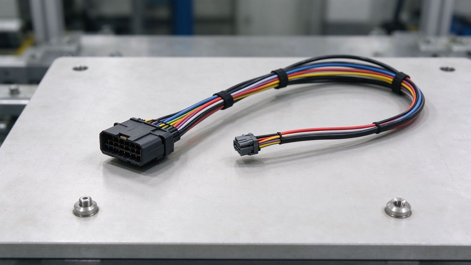
Name a stable reference and the condition in which the assembly is measured. Identify whether the datum is a connector face, mounting feature, fixture location or another approved point. If a fixture is required, show its orientation and the locations that position the harness. A photo or installation view may explain the setup, but it does not replace controlled dimensions or a written measurement method.
For a flexible assembly, state whether it is laid out without tension, held in a fixture or routed through the installed path. Explain how bends and service loops are treated and which retention points constrain the route. The same conductor can present a different length when stretched, relaxed or routed around adjacent parts. Keep the method consistent between design review, sample inspection and production checks.
Which dimensions are acceptance limits?
Not every visible measurement needs to become an acceptance limit. Mark critical-to-fit or customer-controlled dimensions clearly and distinguish them from reference dimensions that communicate overall shape. The responsible design authority should establish tolerances from the interface and application. Do not copy one generic tolerance onto every branch when different connectors or mounting points have different needs.
Where a tolerance stack could affect fit, review the complete route rather than checking each segment in isolation. Consider connector position, breakout, retention and final mating interface together. Identify the feature that controls acceptance and the document containing its approved limit. If a drawing, model and inspection plan disagree, resolve the source of truth before a supplier builds to an assumption.
How should the drawing, model and sample be coordinated?
When both a two-dimensional drawing and a three-dimensional model are supplied, identify their revision relationship and which file controls dimensions, routing or visual reference. The model can help explain orientation and clearance; the drawing can carry explicit dimensions, notes and revision history. The sample inspection record should reference the same released revision and identify the measured feature, result and method.
During sample review, compare the assembly with the documented configuration. Check connector orientation, branch identity, breakout location, retention features and route through the installation space. If a discrepancy appears, record the exact location and condition before requesting a correction. JinHai’s harness quality overview provides inspection context; project-specific acceptance criteria still come from approved drawings and customer requirements.
How should redlines and drawing revisions be closed?
When review identifies an unclear dimension, mark the exact feature on a drawing copy and describe the observed condition. Identify the assembly configuration, measurement method and equipment or fixture. Instead of a note such as “branch appears short,” identify the branch, datum, endpoint and how the installed route affects measurement. The design owner can then decide whether to clarify the drawing, revise the dimension or change the route.
Keep review comments separate from released dimensions until approved. A marked-up drawing can guide discussion but should not silently replace the production revision. Once a change is accepted, update the controlled file, revision note and affected inspection reference together. A comment log should record the feature, question, owner, disposition and whether an approved sample or inspection plan needs review.
Before issuing the new revision, check changed callouts against affected BOM entries, wire identification, connector views and work instructions. Remove superseded values that could be mistaken for current requirements and notify manufacturing and inspection through the agreed document-control process. JinHai’s customized process page describes its drawing review workflow; buyer project documents remain the authority for required geometry and acceptance.
Drawing release review checklist
Confirm part number, revision, date and change summary.
Reconcile connector views with cavity maps and circuit identifiers.
Match dimensions and materials to the BOM and wire list.
Mark provisional information and assign an owner to each open item.
Identify controlled versus reference dimensions and acceptance sources.
Confirm the measuring condition for loose and installed geometry.
Update sample, inspection and document references after approved changes.
Frequently asked questions
Should branch lengths include connectors?
There is no universal convention. State the endpoint used for each controlled dimension and apply it consistently.
Can a sketch support an early quote?
A sketch can support feasibility discussion, but a controlled drawing and circuit data reduce assumptions before sample approval.
How should a three-dimensional route be documented?
Use an installation view, fixture reference or customer-approved routing envelope when it controls fit or movement.


 English
 العربية
 Bahasa Indonesia
 Tiếng Việt





 English
 Vietnamese
 Indonesian
 Arabic
 Spanish