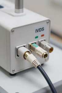
Classic IVDS Cable Application Equipment
Chapter 1: What Are IVDS Cables?
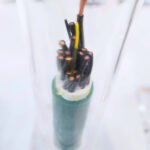
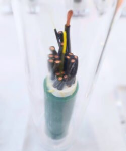
IVDS cables refer to specialized cable assemblies used exclusively in in vitro diagnostic instruments. They consist of multiple conductors, shielding layers, connectors, and protective jackets, and are responsible for transmitting power, control signals, and detection data between the device’s various functional modules.
Unlike standard industrial cables, the core challenge for IVDS cable assemblies lies in the fact that IVD devices contain both precision detection circuits that process low-level signals and high-power actuators that operate pumps, motors, and heaters. Furthermore, these devices must ensure the accuracy of test results in the complex electromagnetic environments of medical facilities. The vast majority of IVD medical devices are classified as Class I, Category B devices, meaning they must handle low-level signals susceptible to interference while also meeting the stringent electromagnetic interference control requirements of medical environments.
Key Features at a Glance
| Feature | Typical Specifications | Description |
Operating Temperature | -40°C to +150°C | Covers standard and high-temperature sterilization environments |
Rated Voltage | 300V AC / 600V DC | Complies with medical device safety requirements |
Shielding Coverage | ≥ 85% (aluminum foil + copper mesh) | Effectively suppresses electromagnetic interference |
Conductor Resistance | ≤ 65Ω/km (AWG24) | Low resistance ensures signal integrity |
Contact Resistance | < 10 mΩ | Gold-plated contact design |
Insulation Resistance | ≥ 100 MΩ (500 V DC) | Ensures electrical isolation safety |
Withstand Voltage | 1500 V AC/min, no breakdown | Complies with IEC 60601-1 safety standards |
Mating Cycle Life | ≥ 5000 cycles | High-durability gold-plated contact design |
Flame Retardant Rating | UL VW-1 | Flame-retardant, low-smoke, halogen-free |
Data Source: Technical Standards for Medical Device-Specific Cable Assemblies
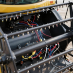
Chapter 2: In Which Devices Are IVDS Cable Assemblies Used?
IVDS cable assemblies are widely used in the in vitro diagnostics field. The following are six typical devices:
- Blood Analyzer
- Chemiluminescence Immunoassay Analyzer
- Biochemical Analyzer
- Coagulation Analyzer
- PCR Analyzer (Gene Amplifier)
- Urine Sediment Analyzer
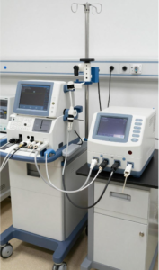
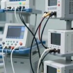
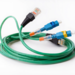
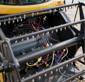
IVDS cables connect a variety of medical devices
Chapter 3: How to Correctly Select the Right IVDS Harness for Your Equipment?
Key Selection Parameters
Wire Gauge and Current Carrying Capacity: Select the wire gauge based on the equipment’s current requirements.
Number of Conductors and Signal Type: Determine the number of conductors based on the interface specifications of the functional modules.
Shielding Structure and EMC Rating: Double shielding (aluminum foil + braided copper mesh) ensures a shielding coverage of ≥85% and is the preferred choice for IVD devices handling low-level signals. IVD devices must comply with the electromagnetic compatibility requirements for Class B equipment specified in GB/T 18268.26-2010.
Insulation and Sheath Materials: Medical-grade PVC is suitable for standard environments; FEP or medical-grade silicone must be used for high-temperature sterilization scenarios; TPE material should be selected when there is a risk of chemical exposure.
Connector Selection: Contact resistance should be less than 10 mΩ, with a mating cycle life of ≥5,000 cycles. Prioritize medical-grade connectors from brands such as Hirose, Molex, and Amphenol, and ensure connectors feature a secondary locking mechanism to prevent loosening due to vibration.
Selection Criteria
| Device Type | Recommended Gauge | Recommended Conductor Count | Shielding Requirements | Special Requirements |
Signal Acquisition | AWG 24–26 | 4–12 conductors | 4–12 conductors | Aluminum foil + braided shield ≥85% | Contact resistance <5 mΩ |
Motor/Actuator | AWG 20–22 | 2–6 conductors | Basic shielding sufficient | Flex resistance ≥100,000 cycles |
Thermal Cycling Modules | AWG 20–24 | Depends on interface | Temperature resistance ≥125°C | FEP or silicone insulation |
| Mixed-Function Modules | Mixed wire gauges | 10–24 conductors | Zone shielding | Compartmentalized routing design |
Customization Options
- IVDS harnesses support a variety of customization solutions:
- Mixing different wire gauges to meet mixed signal and current requirements;
- Zone shielding and compartmentalized routing to reduce signal crosstalk;
- Molded connectors to improve water and dust resistance ratings;
- Providing 100% continuity testing, withstand voltage testing, and insulation resistance testing reports upon shipment to ensure every harness meets the highest quality standards.
Chapter 4: What Are the Serious Risks of Incorrect IVDS Cable Usage?
Risk 1: Signal Interference Causing Drift in Test Results
This is the most subtle yet severe consequence of incorrect IVDS cable selection. When cable shielding coverage is insufficient (below 70%) or grounding design is improper, test values may exhibit random drift of 5% to 20%, leading to false positive or false negative results.
Mitigation: All signal cables must feature a double-shielded structure with a shield coverage of ≥85%, and a single-point grounding scheme must be strictly implemented.
Risk 2: Intermittent Instrument Failures Due to Poor Contact
Poor connector crimping is one of the most common cable failures leading to instrument malfunction;
Mitigation: Select suppliers with strictly controlled crimping processes and require them to provide metallographic cross-section analysis reports of the terminals; Select gold-plated connectors with a mating cycle life of ≥5,000 cycles.
Risk 3: Signal Interruption Due to Cable Wear
During instrument operation, cables subjected to relative motion are highly prone to wear-related failures.
Mitigation: During the cable selection phase, conduct specialized design for routing paths, mounting methods, and bend radii; select cable jackets with high flex resistance or use spiral cables.
Risk 4: Insulation Materials Not Resistant to Chemical Corrosion
IVD devices often experience spills or residue from cleaning solutions and reagents. If the insulation materials are not resistant to chemical corrosion, the jacket may gradually soften, swell, or even dissolve.
Mitigation Method: Use TPE materials in areas likely to come into contact with reagents.
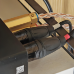
Using the wrong IVDS cable causes the device to display an error
Chapter 5: Summary
As the critical link connecting the processor and actuator in in vitro diagnostic devices, the performance of IVDS cables directly impacts the instrument’s testing accuracy, operational stability, and service life. JinHai invite you to contact our technical team for specific selection recommendations and to request samples for small-batch installation and reliability testing.