Chapter 1: Introduction
In the maintenance, diagnosis, and repair of modern electrical and electronic systems, continuity testing is a fundamental and critical operation. It serves as a quick, direct method to verify whether an electrical current can form a complete, uninterrupted path through a circuit. Simply put, it answers a core question: “Is the circuit conductive?” Whether professional electrical engineers are troubleshooting complex industrial equipment or electronics enthusiasts are assembling a new circuit board, continuity testing serves as the primary step to ensure circuit integrity and proper functionality. This guide will delve into the principles, importance, standard operating procedures, and alternative methods of continuity testing, providing practitioners and hobbyists with a comprehensive and practical manual.
Chapter 2: What Is Connectivity Testing?
Definitions and Fundamental Principles
Continuity testing, also known as continuity check, essentially measures the resistance between two points in a circuit. An ideal closed circuit (such as an intact wire or a closed switch) has an extremely low resistance value, approaching zero. Continuity testing leverages this principle by injecting a small current into the circuit under test via a testing device (typically a multimeter). If the current flows unimpeded from one probe to the other, the device determines the circuit has “continuity,” usually indicated by a beep or displaying an extremely low resistance reading. Conversely, if a break exists in the circuit—such as a severed wire, damaged component, or open switch—current cannot flow. The testing device will indicate an infinite resistance or “Open Loop” (OL) state, signifying the circuit lacks continuity.
Common Application Scenarios
Continuity testing has an extremely broad scope of application, covering virtually all circuit-related fields. Its core value lies in rapidly locating “open circuit” faults. Common application scenarios include:
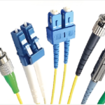
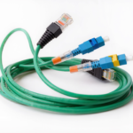
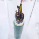
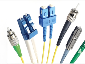
- Inspecting wires and cables: Verifying whether internal conductors within cables are broken.
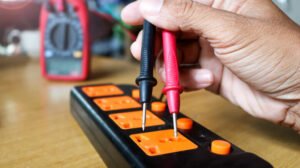
- Testing fuses: Quickly determining if a fuse has blown. A good fuse should exhibit continuity.
- Verifying Switch Functionality: Ensuring switches properly conduct electricity when closed.
- Inspecting Solder Joints and Copper Traces on PCBs: Confirming reliable connections between component leads and the board, as well as the integrity of copper traces on printed circuit boards (PCBs).
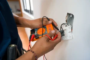
- Confirming Grounding Safety: Verifying a reliable low-resistance connection between equipment casings and grounding wires—a critical safety measure.
Chapter 3: Who Would Want to Do This?
Introduction Continuity testing appears to be a basic “on or off” test but it contains more of one set of logic that determines if the system is functioning correctly and safely.
The first reason is that it forms the basic requirement for circuit functioning. Every electronic device, a flashlight or a computer, however basic or complex, is based on the regulated flow of current through specific paths. A sudden fracture can at once render inoperative the entire or part of the above described circuit. Continuous check of the continuity when installing anticorrosive protection systems, in carrying out repairs, preventive examinations on principal groundings are based a largely verification of physical intactness of the review circuit.
Second, it avoids the possible likelihood of an electric failure. Perhaps it’s not a total disconnect when circuit problems arise. Loose connections, oxidized and broken wires are all common reasons for an intermittent failure — the hardest to establish. Continuity testing–particularly when supplemented with resistance measure ment, as embodied by the invention (FIG. 2), can be used to discover “suboptimal” connection points characterised by unusually high realised resistance values. This ensures that repairs are carried out before they become catastrophic.
Enforcement also greatly improves equipment safety and reliability. The verification of ground continuity is a mandatory measurement according to electrical safety standards. It is such, that during faults (for example, in the case of leakage currents) current can find a safe path to earth and this ensure that users cannot receive an electric shock. Thus, periodic continuity testing — particularly of safety-critical circuits — is a critical factor in insuring the long-term reliability of such equipment and in protecting the safety o f personnel.

Chapter 4: How to Use a Multimeter to Test Circuit Continuity
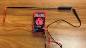
A multimeter, especially a digital multimeter (DMM), is the most commonly used and precise tool for continuity testing. Its operation is simple and intuitive, and the results are reliable.
Preparation: Selecting the Appropriate Multimeter
Most digital multimeters on the market feature continuity testing capabilities. In professional electrical maintenance, selecting a fully-featured digital multimeter (DMM) is standard practice. When choosing one, consider the following points:
- Clear connectivity indicator: This indicator is typically marked with a symbol resembling a sound wave or a diode.
- Buzzer Function: This is an extremely convenient feature. When the circuit is closed, the multimeter emits a beep, allowing the tester to avoid constantly staring at the screen and significantly improving testing efficiency.
- Response Speed: A high-quality multimeter buzzer responds quickly, capable of detecting instantaneous contact.
Detailed Steps
- Safety First: Completely Disconnect the Power Source!This is an absolute rule that must never be violated when performing continuity tests.Under no circumstances should continuity testing be conducted on a live circuit.Not only will this result in erroneous readings due to the circuit’s voltage, but more critically, it may damage the multimeter’s internal precision circuitry or even pose a severe electric shock hazard to the tester.Before testing, the power source must be turned off, plugs must be unplugged, and circuits containing capacitors must be discharged.
- Set the multimeter: Rotate the selector dial to the continuity test setting. Insert the black test probe into the “COM” (common) jack. Insert the red test probe into the jack labeled “VΩmA”.
- Multimeter Verification: Before formal testing, touch the metal tips of the red and black probes together. The multimeter should immediately emit a beep, and the resistance value displayed on the screen should be very close to 0 ohms. This indicates that the multimeter and its probes are functioning properly.
- Connecting Test Probes: Touch the tips of both probes to the two endpoints of the circuit path you wish to test. For example, to test a wire, touch the probes to both ends of the wire.
- Read and interpret test results:
- Hearing a beep/reading close to 0Ω: This indicates a complete, low-resistance path exists between the two points you are testing. The circuit is “”
- No sound/screen displays “OL” (Over Limit or Open Loop): This indicates a break between two points, preventing current flow. The circuit is ‘disconnected’ or “”
Precautions and Frequently Asked Questions
- Isolating the Component Under Test: When testing a component soldered onto a complex circuit board (such as a resistor or fuse), testing directly on the board may cause current to flow through other parallel paths. This can trigger the multimeter’s beep, resulting in a false continuity reading. The most reliable method is to disconnect at least one end of the component from the circuit (e.g., by desoldering a joint with a soldering iron) before testing.
- Interference from Human Body Resistance: During testing, avoid touching the metal parts of both probes simultaneously with your fingers, as the resistance of the human body may affect the accuracy of the readings.
- Wear personal protective equipment: Even when working on de-energized circuits, it is recommended to wear safety gloves and goggles to guard against residual charge or other physical hazards.
Chapter 5: How to Test Circuit Continuity Without a Multimeter
Although a multimeter is the preferred tool, in certain emergencies or situations with limited resources, we can also employ alternative methods for basic continuity checks. While these methods are less precise than a multimeter, they are sufficient for simple diagnostic needs.
Using Simple Tools (such as Batteries and Light Bulbs/Buzzers)
This is a very classic DIY testing method.
- Method: Prepare a battery (such as AA or 9V), a low-power bulb (such as a flashlight bulb), or a low-voltage buzzer, along with two lengths of wire as test leads. Connect the battery, bulb/buzzer, and test leads in series to form a simple open-circuit tester.
- Testing Method: Touch the ends of two test leads to the two terminals of the circuit under test. If the bulb lights up or the buzzer sounds, the circuit is conductive.
- Applicable Scenarios and Limitations: This method is highly suitable for quick continuity checks when professional tools are unavailable. However, its sensitivity is relatively low, making it unable to detect connections with higher resistance (which may result in insufficient bulb brightness or a silent buzzer). It also does not provide any quantitative resistance data.
Using a Dedicated Connectivity Tester
There are specialized pen-style tools available on the market designed for continuity testing, known as continuity testers.
- Features: They are typically smaller and more portable than multimeters, designed specifically for quick “yes/no” They indicate continuity by lighting up or emitting a sound.
- Applicable Scenarios and Limitations: Ideal for tasks requiring frequent, high-volume simple continuity checks, such as production line testing or rapid on-site troubleshooting. Its drawback is its limited functionality—it cannot measure other parameters like voltage or current, unlike a multimeter.
Conclusion
Continuity testing is a fundamental skill in electrical and electronic fields, and its importance cannot be overstated. It serves not only as an effective means to diagnose circuit faults and ensure proper equipment operation, but also as a critical line of defense in preventing electrical accidents and safeguarding personal safety. Whether using a powerful digital multimeter for precise measurements or employing simple homemade tools for emergency assessments, mastering its principles and correct operation is paramount. We strongly recommend incorporating continuity testing into regular circuit inspection and maintenance routines, as it significantly enhances the reliability and safety of equipment and systems. Readers seeking deeper knowledge can further explore interpreting subtle variations in resistance readings and learning to utilize other advanced functions of the multimeter, thereby gaining a more comprehensive grasp of the art of circuit diagnostics.
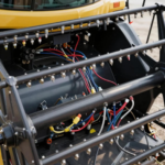
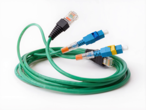
Go for high-quality cable assemblies and wiring harnesses. Jinhai offers you the best solution for wire assemblies.