Chapter 1: What is Continuity Testing?
Simply put, continuity testing uses a multimeter to detect whether the resistance value or current flow between two points in a circuit is continuous.
You can perform this test with a multimeter or ohmmeter. Specialized instruments like resistance testers can also be used. These testing tools feature simple designs, low cost, and include indicator lights to signal current flow.
Chapter 2: Why Perform Continuity Testing?
In electrical systems, continuity testing is an effective method for inspecting various circuit components, such as:
– Checking whether the circuit of a malfunctioning household appliance is conducting properly.
You can test whether two adjacent points on a PCB board are connected.
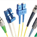
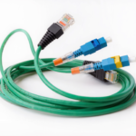
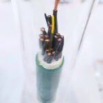
When a circuit break occurs, you can use continuity testing to check wire connections—especially critical for power cords and headphone cables. These cables may appear normal externally but have internal damage.
You can also verify schematics for certain circuits through continuity testing.
Chapter 3: How to Perform Continuity Testing with a Multimeter?
To use a multimeter correctly, first understand what it is and key precautions during operation. Continue reading to learn about multimeters.
Multimeter: A rectangular tool featuring a dial or digital display. Adjusting settings allows you to perform desired tests. The front panel features multiple ports. One is labeled “COM” (Common), serving as the ground connection. Another is “mA/V/Ω” (Measuring Current, Voltage, and Resistance), used for current measurement. Additionally, a “10A” port is available for measuring very high currents.
Next, we’ll explain multimeter operation. What preparations are needed before use?
Pre-use preparations:
l First, rotate the multimeter dial to the Ω (resistance) setting, or directly to “Buzz” mode (if available).
l Next, insert the black probe into the COM port and the red probe into the V/Ω port.
l Briefly touch both probes together to confirm the multimeter emits a beep, indicating it functions properly.
Testing:
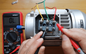
Capacitor Testing:
Capacitors must be fully discharged before testing.
Testing using the resistance (Ω) mode:
l Connect the red probe of the properly functioning multimeter to the capacitor’s positive terminal and the black probe to the negative terminal.
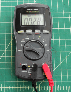
lIf the capacitor is working properly, the multimeter will initially display “0”. The multimeter will charge the capacitor. During charging, the reading will change and may reach infinity or ‘0L’. “0L” indicates the capacitor is fully charged and in an open circuit state.
lA damaged capacitor will typically display a very low capacitance value (short circuit) or infinity (open circuit).
Inductor Continuity Test:
An inductor is essentially a coil and must be removed before testing.
Testing in Resistance Mode:
l Set the dial to resistance mode. Adjust to the lowest possible reading.
l Connect the red and black probes to the positive and negative terminals of the inductor.
lIf the multimeter reads several ohms, the inductor is good.
lIf the initial resistance is unusually high, the inductor may be damaged. If the initial reading is close to zero, the inductor’s coil turns may be too low.


Fuse continuity testing:
Repeat the steps above for cables and wires.
lA zero reading on the multimeter indicates the fuse is intact.
lAn infinite reading indicates the fuse is open (broken).
Switch/Button Continuity Test:
When testing switches, repeat the above steps while testing both the “ON” and “OFF” positions.
First, you must obtain a “zero” reading in the “ON” state and an ‘infinity’ reading in the “OFF” state.
This confirms your switch is functioning correctly.
Conversely, if you get two “zero” or two “infinity” readings under both conditions, the switch is shorted.
In this case, the switch must be replaced to prevent safety hazards.
Chapter 4: How to Perform Continuity Testing Without a Multimeter?
You can use a simple continuity tester to check metal pathways.
This basic tester operates on a straightforward principle: simply touch the metal probe or alligator clip to the wire.
If the circuit is conductive, an indicator light will illuminate or a buzzer will sound.
Similarly, you can test circuits, appliances, or electrical paths within circuits.
Before using this tester, always turn off the power supply, as testing live wires is extremely dangerous.
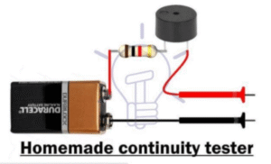
If none is available, don’t worry. You can make your own circuit continuity tester.
Prepare a small 12V battery, a light bulb or buzzer, and connect them to the circuit under test. If the bulb lights up or the buzzer sounds, the path is intact. This method is suitable for low-voltage circuits.
Conclusion
Circuit continuity testing is crucial for repairing large electronic devices. Checking circuit continuity helps you pinpoint any issues with circuit integrity. However, to prevent problems with your electronics, you must take proactive measures early on.
Opt for high-quality cable assemblies and harnesses. JinHai provides you with the best wire harness solutions.