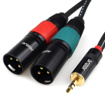
Chapter 1: How Do TRS Cables Cause Loud Stage Noise?
TRS cable assemblies are a type of RF cable assembly。The physical cause of ground loops in TRS cable assemblies is quite clear: when two or more devices are connected to ground via different paths, potential differences between them generate a current in the ground loop. The low-frequency sound produced by this current flow is ultimately amplified by the sound system into audible noise.
Field test data shows that significant ground loop interference can occur when the ground potential difference between devices exceeds 0.1V. In typical stage environments or drier conditions, this potential difference can be 3–5 times higher, or even greater.
Research data indicates that audio cables of different brands and designs can exhibit electrical parameter variations of up to two orders of magnitude: capacitance ranges from 38.72 pF/m to 1252.53 pF/m, inductance from 0.27 μH/m to 27.40 μH/m, and resistance from 5.54 mΩ/m to 43.41 mΩ/m. These significant variations in parameters directly determine the cable’s susceptibility to ground loop interference.
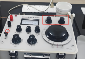
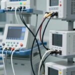
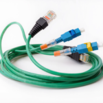
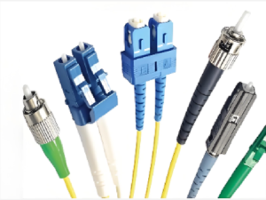
TRS Cable Tester
Chapter 2: How to Mitigate High Stage Noise Using TRS Cables?
Since TRS cables serve as conductive paths for ground loops, such issues can be completely avoided through scientific selection and connection strategies. The following are three effective methods verified by practical testing:
Full-Length Balanced Transmission:
High-quality balanced TRS cables can achieve a common-mode rejection ratio (CMRR) of 72–76.4 dB, which is more than 15 dB better than standard consumer-grade cables. This means that under 1 mV of external interference, balanced transmission can suppress interference at the output to below 0.15–0.25 mV.
Use a ground loop isolator:
Insert an audio isolation transformer into the TRS signal chain to transmit signals via electromagnetic induction while completely disconnecting the electrical connection between the two ends. Test data shows that high-quality isolators can achieve 15–30 dB of audio interference suppression. In high-frequency interference environments such as 400 MHz Wi-Fi, TRS cables with a double-layer shielding structure can control the output noise floor to +1.7 μVrms, whereas standard cables yield +8.3 μVrms—a 74% reduction in noise floor.
Single Power Path:
Connecting all audio equipment to the same power outlet or power conditioner is the simplest method to eliminate ground potential differences. Measurements show that when devices are distributed across different power circuits, ground potential differences can reach 0.5–2 V; however, using a single power source reduces this value to below 0.01 V.
Chapter 3: What Are the Adverse Effects of High Stage Noise?
Here are five quantifiable adverse effects:
SNR Deterioration:
Ground loops can increase a system’s background noise by 10–20 dB. For professional audio systems, this means the SNR drops from 90 dB to 70–80 dB.
Loss of Effective Resolution:
Noise increases from +1.7 μVrms to +8.3 μVrms. For high-resolution recording systems, this equates to a loss of 1.5 bits of effective resolution. This results in the permanent loss of audio detail.
Frequency distortion:
Common-mode noise introduced by ground loops generates noise spikes of 0.5–1.2 μV in the 18–20 kHz frequency band, resulting in the degradation of high-frequency audio.
Malfunction of other equipment:
In extreme cases, interference introduced by ground loops can reach 50–200 mV, which is sufficient to trigger circuit protection in certain electronic devices or cause misinterpretation of control signals.
Auditory Fatigue in Listeners:
Prolonged exposure to a sound field containing 50/60 Hz low-frequency noise causes the auditory systems of listeners and staff to remain in a state of constant tension, accelerating auditory fatigue.
Chapter 4: What Type of TRS Cable Should Be Selected to Minimize Stage Noise?
The following are three specific selection options and their quantitative metrics:
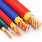
Prioritize cables with high shielding effectiveness:
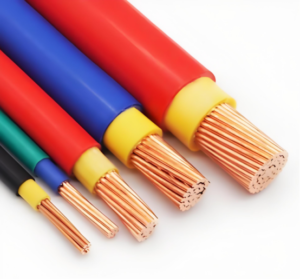
Select TRS cables featuring a dual-layer shielding structure of aluminum foil + high-density braided mesh, with a shielding coverage of 85–96% or higher. Test data shows that a shield with 96% braid coverage can achieve ground resistance as low as <0.02 Ω/m, with an output end baseline noise of only +1.7 μVrms in a 400 MHz interference environment, whereas a competing product with 85% coverage measures +8.3 μVrms. The conductor should be 99.99% oxygen-free copper (OFC), with a recommended silver plating thickness of 1.2 μm or greater, which can reduce resistive loss in the 20 kHz frequency band by 18%.
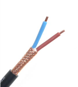
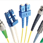
High-Performance Shielded TRS Cable
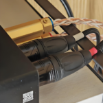
Use gold-plated/silver-plated connectors:
The contact quality of connectors directly affects signal purity. The contact resistance of 24K gold-plated connectors can be as low as 0.8 mΩ (when newly inserted), rising to only 1.2 mΩ after 500 insertion/removal cycles—far below the 3.5 mΩ threshold of standard nickel-plated products. The spring clamping force should reach 1.8 N ± 0.2 N to ensure mechanically stable contact with the TRS connector. When observed on an oscilloscope, standard cables exhibit voltage spikes of 20–50 mV during insertion and removal, whereas high-quality cables remain consistently within ±2 mV.
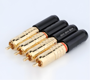
Gold-plated connectors for TRS cable
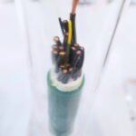
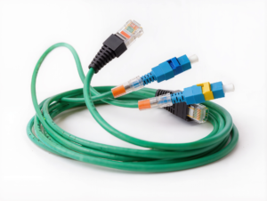
Select a precision twisted-pair structure:
For applications requiring long-distance transmission (>5 meters), choose TRS cables with a dual-core independent twisted-pair structure, with a twist pitch controlled at 8.7 ± 0.3 mm, in compliance with the IEC 60958-3 balanced transmission standard. This structure exhibits frequency response fluctuations of less than ±0.3 dB within the 20 Hz–20 kHz frequency range, far superior to the ±1.2 dB of standard two-conductor cables. In balanced-to-unbalanced conversion scenarios, the signal-to-noise ratio of a four-conductor twisted-pair structure is 12 dB better than that of traditional two-conductor cables.
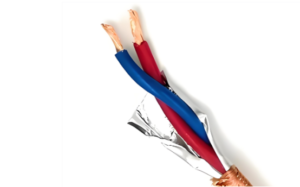
The twisted-pair structure of TRS cables
Chapter 5: Conclusion
As the core connection medium in professional audio systems, the electrical parameters of TRS cables (capacitance, inductance, resistance, and shielding effectiveness) directly determine the system’s susceptibility to ground loop interference. By adhering to fully balanced transmission (CMRR ≥ 72 dB), utilizing isolators appropriately (15–30 dB of interference suppression), and providing high-quality cables (shielding coverage ≥ 96%, contact resistance < 1 mΩ), JinHai can create a stable, flat-response, and long-term reliable audio system for your stage.